chinese
 english

Diesel engine water pump and its structure
Article provenance:Hai Rui ZhonglianPopularity:Publication time:2020-03-25 09:15
Diesel engine water pump and its structure
Mixed flow pump (HB)
Mixed flow pump is a kind of pump between centrifugal pump and axial flow pump. Its working principle is to use centrifugal force and thrust to make water rise, so as to achieve the purpose of pumping.
Structure of mixed flow pump: different guide structures can be divided into volute type and guide vane type
Tubular pump
What are the components of a pumping unit?
It consists of diesel engine water pump, power engine, transmission mechanism, pipeline and various accessories.
Performance parameters of water pump:
(1) Flow; (2) navigation; (3) speed; (4) power; (5) efficiency (6) allowing vacuum or cavitation.
(1) Flow: also known as water output and drainage. It refers to the unit time (1 second or 1 hour) for entering the liquid volume or mass pipeline from the pump outlet.
The volume of liquid is the volume flow expressed in Q, and the mass of liquid is the mass flow expressed in G, expressed in the unit of volume flow: LTS, m3?
Massflowunit:kg/st/hconversion1L/S=0.001m3/s=3.6m3/h,1kg/s=3.6t/h
Relationship between volume flow and mass flow: q = g / -- liquid density, unit: kg / m3.
The actual flow at the original outlet is called the actual flow. The flow indicated on the water pump nameplate is the design flow of the water pump, also known as the rated flow.
(2) Head: the head of the pump is the concept of energy, which refers to the energy added by the unit weight of the liquid flowing through the pump. In "H" in meters
H = HXHY; HX: suction head; hy: outlet head.
H = h demand = h actual + H loss h loss = h pressure loss + H absorption loss, H loss - loss head
The height at which a pump can draw up water is called the suction head.
The water pump can lift the water pressure from a high place, which is called pressurized water lifting.
Datum of calculation height: the center line of pump shaft is the boundary of centrifugal pump.
The vertical axial flow pump is based on the water surface of the water inlet tank
(3) Speed: refers to the number of revolutions of pump impeller per minute. In N, in R / min.
The speed on the pump nameplate is called rated speed.
When the speed changes, the other five performance parameters of the pump also change.
(4) Power: refers to the work done by the pump in unit time (seconds). In N, kW, (HP)
1 HP = 0.736kw1kw = 1.36 HP
Divided into: shaft power, effective power, matching power.
Input power: that is, the power transmitted from prime mover to pump shaft, also known as shaft power. Use N axis
The power shown on the performance table or nameplate of the pump is the shaft power. N axis = n effect + N loss
Pump power loss n mainly includes: mechanical loss, volume loss and hydraulic loss.
Mechanical loss: pump rotation, pump shaft and bearing, packing, impeller rotation and water friction, etc.
Volume loss: the clearance between impeller and pump body allows a small amount of water to return to impeller inlet and stuffing box.
Hydraulic loss: friction loss of water flow in the inlet and outlet channels and blades, and loss caused by water flow speed and direction.
2 output power: the net power of water flowing out of the water system. Also known as effective force. Has an n effect
N effect = rqh / 102 (kw) n effect = ρ GQH / 1000 (kw)
ρ: Water density kg / M3G: gravity acceleration M / s2q: flow m ~ 3?
H: Head MR: density kg / L
The difference between input power and output power is the power loss of the pump.
3 matching power: refers to the power figure of the generator that the water pump should be. And n
The matching power is 11 ≤, which is 13 times of the shaft power.
N Match = (1.1? 1.3) N axis
(5) Efficiency: it is the ratio of the effective power of the pump to the shaft power. It is represented by η and the size is represented by%. This is an important technical and economic indicator.
_=N effect / N axis * 100% = rqh / 102N axis * 100%.
The efficiency of the water pump nameplate corresponds to the efficiency when passing the design process. For maximum efficiency.
The total efficiency of the pump is the product of three efficiency, namely volume efficiency, hydraulic efficiency and mechanical efficiency.
At present, the efficiency of domestic small pump is 70% / 85%, and that of large pump is 85% / 90%.
(6) Allow to apply vacuum: refers to the minimum pressure allowed by the pump when there is no cavitation. Expressed in HS, in m water column
Cavitation margin: refers to the excess energy of unit volume liquid at the pump inlet exceeds the vaporization pressure. Unit H: meter water column.
The more vacuum the pump is allowed to absorb (or the smaller the cavitation margin), the better the cavitation performance of the pump.
Working parameters of water pump
Numerical Chinese Pinyin numerical alphabet
Pump inlet represents pump flow pump head or 1 / 10 specific speed ABC represents pulse
Or processing degree of outlet diameter
1 centrifugal pump: B or Ba represents single stage single suction cantilever
S or sh refers to single-stage double suction horizontal type
D -- multi level
2-axis pump: zlbzwbzxb
Z axial flow l-vertical w-horizontal x-oblique flow
B-blade is semi regulated, q-blade is fully regulated.
3 mixed flow pump: hbhlhw
H-type mixed flow pump B-type horizontal L-type vertical
Pump speed triangle: V absolute = V circle + V phase
The angle α between the absolute velocity and the circumferential velocity is called the absolute liquid angle.
The β angle of relative velocity in the opposite direction to the circumferential velocity is called the relative liquid angle.
Similarity law of water pump
The condition is that the two pumps meet the geometric similarity, similar motion and similar dynamics, and their flow, head and shaft power follow certain change rules.
The first similarity law: QP / QM = (DP / DM) 3.np/nm
The second similarity law: HP / HM = (DPNP / dmnm) 2
Third phase similarity law: NP / nm = (DP / DM) 5 (NP / nm) 3
Proportion law of water pump:
Q1/Q2=N1/N2H1/H2=(N1/N2)2N1/N2=(N1/N2)3
Specific speed: specific speed is the comprehensive data comparing pump performance. It refers to the impeller speed of the die head pump is 1m, the power is 1 horsepower (HP) (0.735kw), and the flow rate is 0.75m3/s.
NS=3.65n=Q/H3/4
n: Rated speed of water pump, / min; H: rated lift of water pump, m; H / Z: Z refers to water pump series; Q: rated flow of water pump, m3 / s, Q / 2 shall be adopted for double suction pump.
The specific speed is related to the outlet water condition.
Actual performance of water pump
The relation curve between flow and pump head is a curve that decreases with the increase of flow.
The lift curve of centrifugal pump drops more slowly, and the lift curve of axial flow pump drops more steeply.
Power curve: the power curve of centrifugal pump is rising curve, that is, the power increases with the increase of flow. The power curve of axial flow pump is a decreasing curve, that is, the power decreases with the increase of flow rate.
Efficiency curve: the highest efficiency corresponding to a flow is called the highest efficiency point.
The range between the flow points corresponding to the two points with the maximum efficiency point reduced by 5% ~ 8% is called "high efficiency area", in which the operation of the pump is expected to play a greater role.
The power flow curve of centrifugal pump increases with the increase of flow. When the flow is small, the power of the pump is small, so when the centrifugal pump starts, it can close the valve and start, so that the motor starts smoothly when the power is small. Then gradually open the valve for normal operation.
When the flow of the axial flow pump is small, the shaft power is very large, which can reach about 2 times of the rated power. For axial flow pumps, the valve cannot be closed and must be started to reduce the starting power.
Cavitation and protection of water pump
Cavitation: also known as cavitation, is a special physical phenomenon of liquid.
Effect of air erosion on pump performance:
1. The performance curve is reduced. The flow part is peeled off. Cavitation produces vibration and noise;
There are four types of cavitation:
The first type of cavitation; the second type; the third type; the fourth type.
Class I and II gas etching is called "harmless cavitation", class III cavitation is called "harmful cavitation", and class IV cavitation is called "interstitial cavitation".
Basic cavitation residue (critical cavitation residue): when cavitation is imminent, the energy of the pump suction device minus the excess energy of the suction height and the loss of the suction pipe, which exceeds the residual energy of the local gasification pressure at that time, expressed as △ H.
"△ H" = μ V & lt; garbage & gt; / 2G + λ W & lt; garbage & gt; / 2G μ: dynamic coefficient, usually μ = 1.0 ~ 1.2;
λ: Cavitation coefficient.
Effective cavitation allowance (equipment cavitation allowance): refers to the abundant energy of liquid at the pump inlet exceeding the gasification pressure under the current temperature, expressed as.
△ h package = PA / ρ g-h suction - h suction - PV / ρ G
Allowable cavitation allowance: refers to the appropriate increase of cavitation allowance to ensure that the pump will not produce cavitation. Expressed as △ H.
The smaller the allowable deviation of cavitation, the better the cavitation performance of the pump.
When "△ H" fits "≥" △ H ", air erosion will not occur on the pump, and vice versa.
Allowable suction vacuum height: the maximum vacuum allowed at the pump inlet to ensure that the lowest point of pump pressure will not produce (or produce weak cavitation harmless to pump operation).
Cavitation similarity law:
It reflects the relationship between cavitation performance and similar motion conditions. According to the similarity theory of two similar pumps, the relationship between their cavitation allowance is derived.
△ hpro / △ hprom = (nd / nmdm) 2 ratio effect △ HR1 / △ HR2 = (N1 / N2) 2
Cavitation specific speed
The cavitation performance of water pump is an important parameter to reflect the cavitation performance of water pump, and also an important basis to judge the similarity of pump cavitation. Similar to the calculation of pump specific speed, the cavitation specific speed of pump can be derived from the similar theory of pump.
c≥3.65NQ/△hp.3≈4
Q: maximum efficiency point flow, m3 ≤ s, double suction pump Q ≤ 2; n ≤ R ≤ min; △ h Specialty: NPSH, M.
The higher the cavitation ratio, the better the cavitation resistance
Determination of installation height of water pump:
Calculate the allowable vacuum height of the root pump [HS]:
HX = [HS] - hx-v / 2gv / 2G: velocity head, HX: suction pipe loss head m,
HX: installation height of water pump M
Prevention and improvement of pump cavitation
1. Improve the ability of diesel pump to resist wind erosion:
(1) Guarantee from two aspects of design and manufacturing process;
(2) In order to meet the requirements of using place, operating conditions and operating conditions without cavitation, it is better to purchase water pumps made of materials with good cavitation resistance.
2. Take some measures for pump device and pump operation:
In order to minimize unnecessary pipe accessories, such as bottom valve, elbow, gate valve, etc., the pipe should not be too long and the inlet diameter should be large.
Reasonable design into the pool, water diversion structure, so that the flow of water into the pump smoothly, improve the inlet flow situation.
(3) In the process of operation, the sewage barrier should be cleaned in time to avoid excessive drop of the water level of the pump station.
If necessary, the pump speed can be reduced properly on the premise of meeting the operation requirements.
5 the over current components damaged by cavitation can be repaired by surface protection technology.
_For the important diesel engine water pump, stainless steel and other anti cavitation materials are used to make the water pump.
Water pump condition regulation:
1. Variable speed adjustment; 2. Variable diameter adjustment; 3. Variable angle adjustment.
Variable angle adjustment mode: 1 fixed, 2 half adjustment, 3 full adjustment.
Full adjustment: divided into oil pressure adjustment and mechanical adjustment.
Full adjustment features:
1. It is a relatively economic regulation method to keep the pump operation efficiency constant in a large flow range.
2. The engine can always run at full load as required. High efficiency, more pumping, long-term full load, improve motor efficiency and power factor.
3. The pump angle is small to start, the resistance moment is small, the starting load of the power machine is reduced, and the unit is easy to start. Before stopping, the installation angle of the blade is reduced, which can reduce the reverse flow speed when stopping.
Fixed wet chamber type
Block based
1、 Separate base pump house
Features: the foundation of the house is separated from that of the unit. Form: slope type, retaining wall type, mixed type, suitable for the situation of small water level change, stable water source slope and installation of horizontal units.
2、 Dry room pump house
Features: the floor and side wall of the pump house are poured with reinforced concrete as a whole to form an impermeable pump house. It is suitable for the situation that the water level of water pump changes greatly or the suction range is small. Shape: rectangle, circle. It is divided into two layers: the upper layer is equipped with electrical equipment, and the lower layer is equipped with pump, power supply and pipeline.
3、 Wet chamber pump house
Through the open inlet tank, the water inlet tank is located at the lower part of the pump room, and the pump is placed in the water tank to form a pump room with a free surface. It is divided into upper motor layer and lower water pump layer.
Form: pier wall type, bent type, cylindrical type, open outlet type.
4、 Block based pump house
Features: the foundation of the pump, the air inlet and the floor of the pump station are injected with reinforced concrete to form the foundation of the whole pump station. It can be divided into two types: comprehensive type and classification type.
The pump house is divided into four layers: top-down motor layer (motor and distribution equipment), coupling layer (coupling, cable, oil and gas, water pipeline), pump layer (water supply and drainage pump), inlet channel layer (water inlet channel, drainage corridor).
Internal layout of pump house:
Horizontal unit: divided into single column and double column
Distribution equipment layout: centralized layout (single end, single side), distributed layout.
Intake structure:
It mainly includes: intake gate, approach channel, forebay and intake pool, etc.
Function of diversion channel: it is an open channel connecting the water source and the pump station to ensure the ability to enter the water, the flow balance is stable and the loss of water is small.
Design requirements for approach channel:
1. There must be enough water transport capacity to meet the requirements of diversion flow.
2. The complexity of geological structure should be avoided as much as possible. In the case of large permeability and potential collapse, the canal should be located on the excavated foundation, occupying less arable land.
3. Sewage, sand, sand cleaning and ice blocking facilities must be provided to prevent dirt, harmful sediment and ice from entering the forebay.
4. The forebay and inlet tank shall have good water flow conditions and small kinetic energy loss. In order to prevent erosion and deposition, the channel velocity should be less than the non erosion and deposition velocity and not more than the non erosion and deposition velocity.
Geometric parameters of approach channel:
1. Try to use the forward water volume, that is, the center line of the water diversion channel is in line with the center line of the forebay and the water inlet pool.
2. The curve radius of the upper channel shall not be less than 5 times of the channel water surface width, and that of the left channel shall not be less than 2.5 times of the channel water surface width. There should be a straight line between the end of the curve and the entrance of the forebay, which is about 10 times the width of the channel.
3. The intersection angle between the center line of diversion channel and the river center line shall be controlled between 30 and 50.
The function of forebay: smooth diffusion water flow, the water flow of diversion channel is uniformly transmitted to the inlet tank to provide good water absorption conditions for the pump; when the pump flow changes, the volume of forebay plays a certain role in regulating, so as to reduce the water level of forebay and the fluctuation of diversion channel.
Design requirements for forebay: as above
Geometric parameters of forebay:
1. The diffusion angle of forebay is generally 20 μ U40.
2. Forebay length: l = (B-B) / 2tg α / 2B end width; B cell width; α diffusion angle
3. The bottom slope of forebay shall be selected within the range of 0.2 ≤ 0.3.
4. Generally used for mortar masonry or dry stone bottom protection, slope protection.
The function of the water tank: (1) provide good water absorption conditions for the pump. (2) When repairing the water pump or suction pipe, cut off the water flow. (3) Set garbage rack to intercept the dirt in the water.
The design requirements of the water intake pool are as follows: (1) the water flow velocity of the water intake pool is small, generally controlled within 0.5m/s; (2) the velocity distribution of each section of the water intake pool is uniform. (3) The boundary of the inlet pool is basically the same as the flow boundary streamline in the pool, and the vortex and reflux are eliminated as far as possible.
Geometric parameters of the pool: (1) height of suspended solids h, suspended solids = 1 / 4D, D: inlet angle diameter. (2) Pool length L = 4.5d (3) pool width b = (2-3) H suspended solids (4) submergence depth h = (0.8-1.1) d
Air inlet shape: elbow shape, bevel shape, bell shape, vacuum disk shape. There is one-way access and two-way access.
Outlet structure: including outlet pool, outlet channel, water conveyance channel and closure facilities
Outlet: This is a connecting building connecting pressure pipe and irrigation main pipe or drainage pipe.
The function of the outlet pool is to eliminate the excess energy of the outlet pipeline and make the water flow smoothly and evenly into the channel or air area; when the unit stops working or the pipeline is damaged, prevent the water flow in the channel or air area from flowing back through the pipeline; in some cases, ensure that the water flow is divided into multiple main canals at the same time.
Design requirements for water outlet tank:
Pressure box: it is generally composed of pressure box, pressure culvert and flood gate.
Outlet pipe: used to connect the pump outlet and outlet water tank.
Outlet: the passage connecting the pump blade outlet and the outlet pool, with short length, large change of section shape, and structural connection with the pump room.
It is divided into: siphon outlet channel, straight outlet channel and inclined outlet channel.
Cut off mode: knock - check valve. After startup, it will automatically open under the impact of water flow. After shutdown, it will be automatically closed through the deadweight and backflow function of flap door.
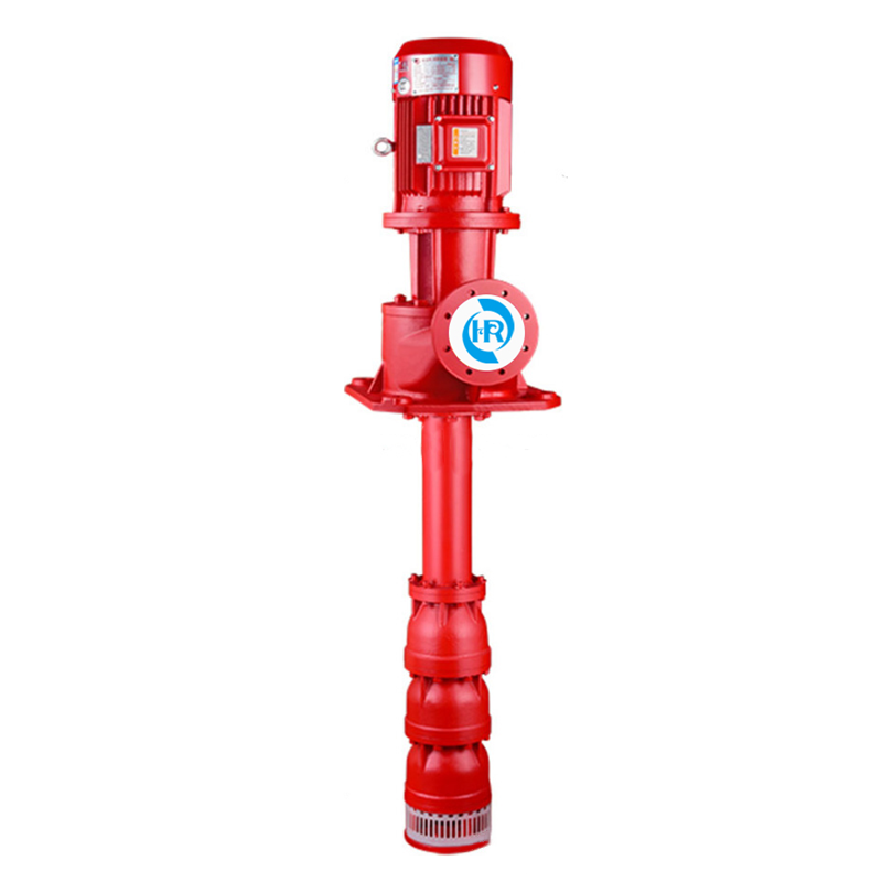 Product Brief XBD / g-hrzl axial flow deep well fire pump (long shaft deep well f...